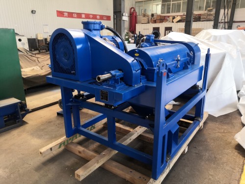
Shale Shaker Application in Energy Infrastructure Projects

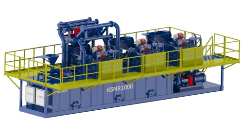
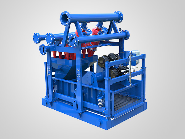
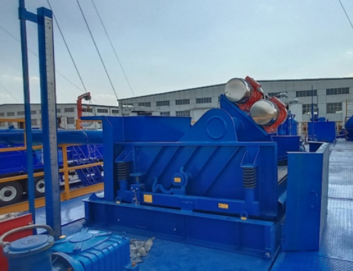
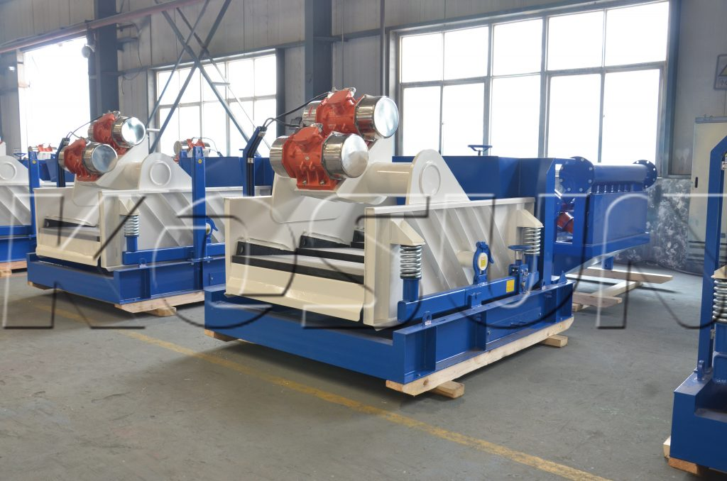
Shale shakers are the first line of defense in solids control for energy infrastructure projects. By efficiently separating drill cuttings from drilling fluid, they directly influence operational efficiency, environmental compliance, and cost management. In large-scale applications such as pipeline installations, well pad construction, and directional drilling, reliable solids removal is non-negotiable. These high-frequency vibrating screens condition drilling fluid for reuse, reduce waste volumes, and help maintain borehole stability. KOSUN offers rugged shale shakers engineered for reliable performance in demanding energy infrastructure projects.
Core Functions and Operational Benefits

The primary function of a shale shaker is to separate solids from drilling fluid using high-frequency vibration. Larger cuttings are retained while clean fluid returns to the active mud system. This first line of defense protects downstream equipment — desanders, desilters, and centrifuges — from excessive wear and premature failure.

In remote energy projects where logistics are challenging, an efficient shale shaker reduces costly fluid dilution and disposal, minimizes environmental footprint, and lowers handling costs. Proper screening also improves on-site safety by managing slurry pits, reducing spill risks, and preventing hazardous cutting buildup. By optimizing solids removal, shale shakers deliver measurable gains in equipment longevity, safety, and cost efficiency.

Selection Criteria for Project Success

Choosing the right shale shaker requires evaluating several factors. Screen mesh size must match formation geology and balance fluid throughput with separation efficiency. Flow capacity must align with rig pumping output to prevent bottlenecks.

Motion type matters: linear-motion shakers excel with fine solids or sticky clays, while elliptical-motion shakers offer better fluid recovery under variable conditions. Durability features include robust 24/7 construction, tool-free screen replacement, and weather resistance. Environmental adaptability ensures reliable performance in extreme heat, cold, humidity, or dust — typical of large-scale pipeline and directional drilling projects.

Integration with Modern Drilling

Modern energy projects integrate shale shakers with digital monitoring systems. Sensors track vibration, flow rates, and screen integrity, delivering real-time data for predictive maintenance — identifying issues before they cause downtime. As drilling fluids become more complex, shale shakers must continually adapt to ensure optimal wellbore stability and consistent drilling progress.

KOSUN’s Commitment to Quality

KOSUN provides rugged shale shakers built for 24/7 operation . They deliver efficient separation, easy maintenance, and reduced waste, helping project managers achieve more with less environmental impact.

Conclusion

Shale shakers are indispensable for efficient solids control in energy infrastructure projects. By removing solids early, they protect downstream equipment, enable mud recycling, ensure environmental compliance, and prevent wellbore instability. With advances in screen technology, automation, and energy efficiency, modern shale shakers are essential for improving drilling performance and minimizing operational risks. KOSUN is committed to providing high-performance shale shakers and expert support to help customers achieve their project goals.
Drilling Fluid Jet Mixer: The Ultimate Guide to Efficient Mud Mixing

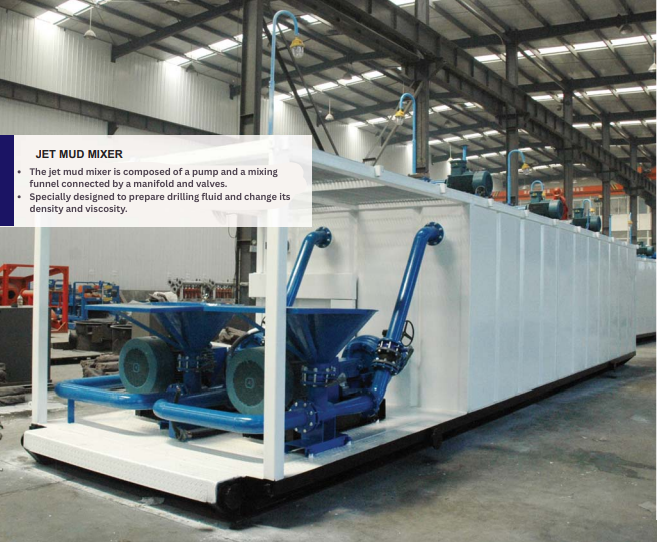
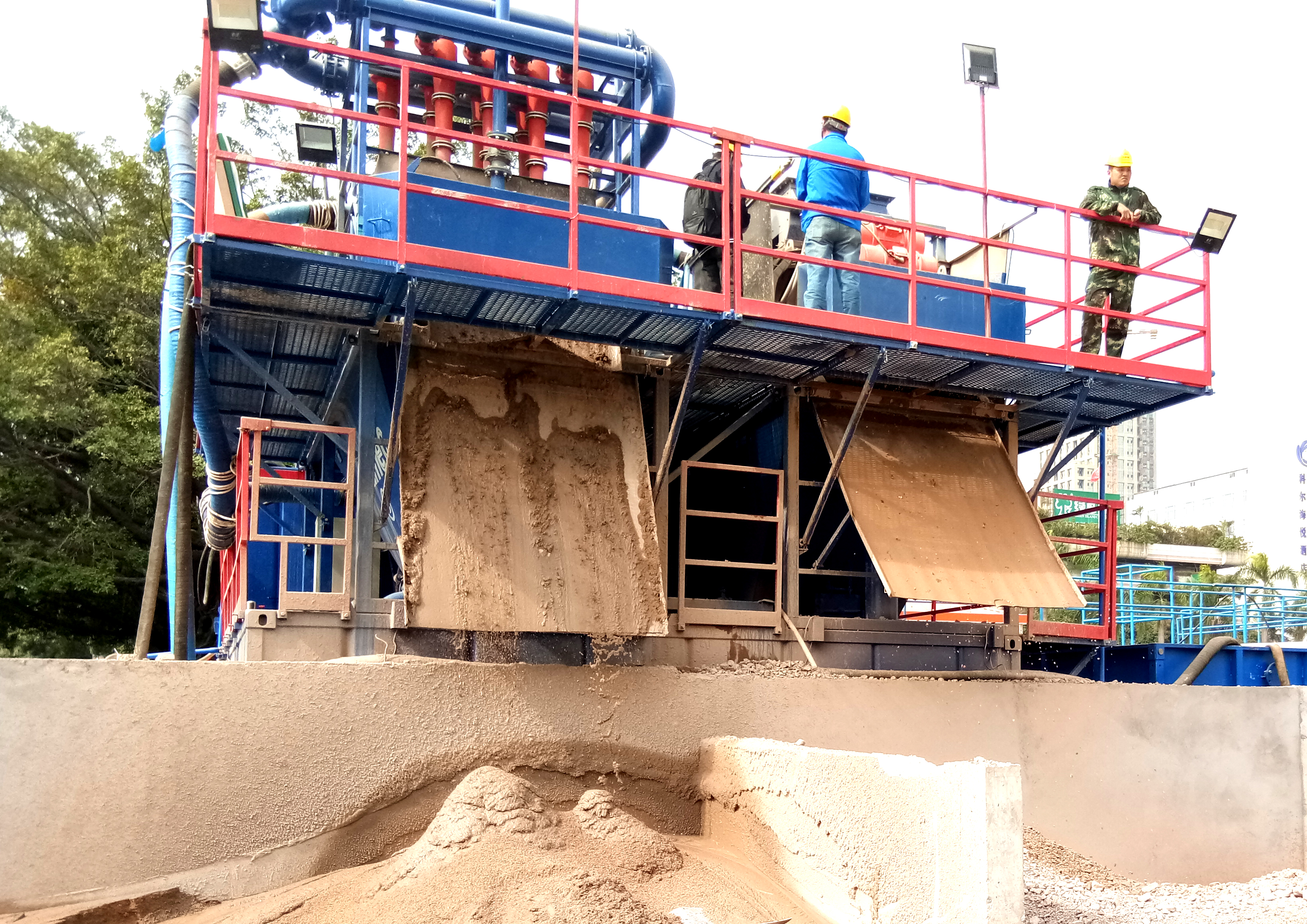
The Drilling Fluid Jet Mixer is a mud mixing funnel designed using the Venturi principle. Also known as a Venturi drilling mud mixing hopper, its main components include a nozzle, mixing chamber, Venturi tube, feeding hopper, butterfly valve, and sand pump or shear pump. The drilling mud mixing hopper is widely used in oil drilling, solids control, trenchless construction, and other applications. It mainly helps operators prepare drilling fluid and adjust key properties such as density, viscosity, and water loss. It is one of the specialized oilfield equipment for weighting drilling fluid. The jet mud mixer is equipped with sand pumps and pipelines to form a jet mixing device. KOSUN offers high-performance drilling mud mixing hoppers engineered for efficient mud preparation and conditioning.

Working Principle of Drilling Fluid Jet Mixer

After the nozzle ejects the liquid, the liquid flows through the mixing chamber and enters the shear tube. Add the material to the mixing chamber through the funnel. The nozzle-driven liquid flow then carries the material into the shear tube, where the material disperses and mixes with the liquid. The liquid flows out of the shear tube and enters the circulation tank.

The shear tube is a hollow tube that gradually expands according to a certain curved surface. Its main function is to increase the shear force of the liquid inside the tube, which helps disperse the material more effectively. The mixed liquid then flows into the circulation tank.

The shear tube actually uses the Bernoulli effect of “fast flow, low pressure; slow flow, high pressure.” Because the nozzle sprays the liquid from the mixing chamber at high speed, the pressure drops as the liquid exits the nozzle. When the liquid enters the shear tube, the cross-sectional area gradually increases, reducing the flow velocity and increasing the pressure.

KOSUN Drilling Fluid Jet Mixer are engineered with precision components to ensure optimal mixing efficiency and consistent fluid properties.

Installation of Drilling Mud Mixing Hoppers

After mixing, the drilling fluid creates significant pressure loss. Therefore, it should discharge the mixed drilling fluid directly into the drilling fluid tank. Install the hopper on top of the drilling fluid tank, or at another elevated position, to allow the mixed drilling fluid to flow directly into the tank without requiring it to climb.

When installing the drilling mud mixing hopper at an elevated position, use a hoist or cantilever crane to lift the drilling fluid materials to the hopper.

When installing the drilling mud mixing hopper at a low position, design a suitable climbing angle and connect the outlet directly to the drilling fluid tank. This configuration helps prevent drilling fluid from overflowing from the funnel.

The Drilling Fluid Jet Mixer typically uses an electric mixing pump for direct drive. If the mixing effect is poor, adjust the distance between the hopper nozzle and the outlet end to achieve optimal mixing performance.

Conclusion

The Drilling Fluid Jet Mixer is an essential component of modern solids control systems, enabling precise control of drilling fluid properties through efficient mixing and shearing. By understanding its working principle and proper installation practices, operators can maximize mixing efficiency and maintain optimal drilling fluid performance. KOSUN provides reliable drilling mud mixing hoppers designed for long-lasting performance in demanding drilling environments.

Slurry Separation Plant: Essential Solutions for TBM Tunnel Efficiency

The Importance of Slurry Separation Plants for Tunnel Boring Machines

Tunnel construction has become an essential aspect of modern infrastructure development, allowing for the creation of subways, highways, and utility tunnels without disrupting surface activities. A critical component of this process is the Tunnel Boring Machine (TBM), which excavates tunnels through various geological conditions. One of the significant challenges faced during tunneling operations is the management of excavated material, commonly referred to as slurry. This is where a slurry separation plant comes into play, playing a vital role in the efficient and environmentally responsible management of excavated materials.

A slurry separation plant is designed to process the mixture of soil, rock, and water produced by the TBM during excavation. The slurry is typically used in conjunction with Earth Pressure Balance (EPB) TBMs or slurry shield TBMs. These machines use the slurry to maintain pressure at the tunnel face, counteract groundwater ingress, and transport excavated material away from the machine. However, to continue efficient tunneling operations, the slurry must be treated and reused. KOSUN offers advanced slurry separation plants engineered for high-performance TBM operations.

How a Slurry Separation Plant Works

Screening involves passing the slurry through screens that filter out larger particles. The remaining slurry then moves to settling tanks, where sedimentation occurs. In this phase, the heavier solids settle at the bottom of the tank, forming sludge that operators can dispose of or process further. Meanwhile, the system collects clarified water from the top and reuses it in subsequent tunneling operations.

Treatment systems may also use filtration processes, especially when finer particles require separation from the water. Advanced filtration systems, such as membrane filters, can achieve a high level of purity, ensuring that the recycled water meets the required standards for reuse. Companies can manage treated solid waste in several ways, depending on its composition, including stabilization, recycling, or safe disposal according to local regulations.

Benefits of a Slurry Separation Plant

The benefits of implementing a slurry separation plant in tandem with TBM operations are manifold.

Firstly, the recycling of water significantly reduces the demand for fresh water sources, which is particularly beneficial in regions where water scarcity is a concern. Secondly, effective handling of excavated materials minimizes the risk of environmental contamination and adheres to strict regulations concerning soil and water quality. Additionally, the efficient management of slurry can lead to cost savings in disposal fees and reduce the environmental footprint of construction activities.

Moreover, the use of a slurry separation plant enhances the operational efficiency of TBM-related projects. By allowing for a continuous and automated treatment process, these plants can keep up with the high rate of excavation, reducing downtime and improving productivity. As the global focus on sustainable development intensifies, the construction industry finds itself compelled to adopt cleaner technologies and methods. Slurry separation plants represent a forward-thinking approach to resource management, aligning with broader environmental goals.

KOSUN equips its slurry separation plants with advanced automation and high-efficiency separation technologies to maximize water recovery and minimize waste.

Conclusion

In conclusion, a slurry separation plant is integral to the successful operation of tunnel boring machines. It provides an effective solution to manage excavated materials, highlights the importance of recycling, and contributes to the sustainability of tunneling projects. As infrastructure development continues to grow, the role of these plants will become increasingly crucial, ensuring that the construction industry adheres to environmental standards while meeting the demands of modern society. The evolution and improvement of slurry separation technology will undoubtedly play a significant part in shaping the future of underground construction. KOSUN provides high-performance slurry separation plants and expert support, helping customers achieve their operational and environmental goals.

Slurry Separation System: Technical Application and Value Analysis for Construction

The rapid growth of urban infrastructure projects, including shield tunneling, deep piling, and trenchless piping, has made effective construction slurry management critical for maintaining project timelines and meeting environmental compliance requirements.The slurry separation system has emerged as the industry-standard solution for efficient solid-liquid separation. KOSUN offers advanced slurry separation systems designed to meet the demanding needs of modern underground construction.

Technical Core: Multi-Stage Solid-Liquid Separation Process

The slurry separation system is an integrated system of solids control units designed for slurry recycling and waste minimization:

Pre-treatment: Scalping screens remove bulk gravel and clay clumps to protect downstream equipment.

Sand & Silt Removal: Desander and desilter hydrocyclones utilize centrifugal force to separate medium-to-fine particles.

Dewatering: For high-clay slurry, chemical conditioning promotes flocculation. Decanter centrifuges and filter presses produce low-moisture filter cakes for easy disposal.

Fluid Reuse: Purified liquid is pumped back for immediate reuse, maintaining a closed-loop operation.

KOSUN’s slurry separation systems integrate high-quality components for reliable, continuous performance in demanding construction environments.

Professional Alignment with Industry Application Scenarios

Slurry separation systems offer high adaptability across four core underground engineering sectors:

Slurry Balance Shield (TBM)

The slurry separation system handles high flow rates while precisely controlling slurry density and viscosity to maintain stable face pressure. KOSUN’s systems are engineered for the demanding conditions of TBM tunneling.

Bored Piling

Provides compact, rapid-deployment solutions for rotary, reverse circulation, and impact drilling. KOSUN designs its piling systems for efficient solids control in confined urban sites.

Diaphragm Walls

Supports trenching with hydraulic grabs or cutters, ensuring slurry stability and trench quality. KOSUN’s diaphragm wall systems deliver consistent performance in challenging ground conditions.

Trenchless Construction

Rapidly purifies slurry in HDD and pipe jacking to minimize urban environmental impact. KOSUN designs its trenchless systems for mobility and efficiency in space-limited environments.

Value Realization: Compliance and Cost Optimization

Environmental Benefits

Slurry separation systems achieve waste minimization at the source, eliminating the pollution risks of traditional mud pits and meeting green construction standards.KOSUN designs its systems for closed-loop operation, minimizing environmental impact.

Economic Benefits

Recycling significantly reduces fresh water and bentonite costs. In addition, dewatered filter cakes reduce waste volume and transportation costs, improving overall operational efficiency.KOSUN’s systems deliver measurable ROI through reduced material consumption and disposal costs.

Conclusion

The slurry separation system is an essential component of modern underground engineering. Optimal system selection requires a scientific analysis of the excavation strata to balance performance and cost-effectiveness. KOSUN provides customized designs tailored to global geological conditions and specific onsite requirements, ensuring reliable performance and maximum value.

Best Practices for Operating Oilfield Mud Cleaning Equipment

Deep-well drilling requires precise surface fluid management. As drilling mud circulates through the wellbore, it returns carrying drilled solids, reactive clays, and abrasive sands. While shale shakers remove large cuttings, fine and ultra-fine particles often remain in the system. Mud cleaning equipment provides the secondary purification needed to remove these contaminants and maintain optimal mud performance.

Proper operation requires balancing fine-particle removal with the preservation of valuable drilling fluids and weighting materials. When managed correctly, mud cleaning equipment prevents the buildup of abrasive solids that accelerate wear on downhole tools, damage mud pumps, and reduce drilling efficiency.

Technical Performance of Mud Cleaning Equipment

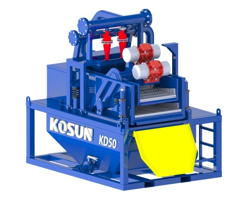
Modern mud cleaning equipment combines hydrocyclones with a high-frequency vibrating screen to provide efficient secondary solids control while minimizing equipment footprint.

Drilling mud is pumped into hydrocyclones, where centrifugal force separates heavier solids from the fluid. Clean mud exits through the vortex finder and returns to the active system, while concentrated solids discharge onto fine-mesh screens for final separation. This two-stage process effectively removes harmful sand and silt while retaining valuable weighting agents such as barite.

Optimizing Throughput Capacity

Peak performance depends on maintaining stable feed pressure throughout the system. Treating the mud cleaner as part of an integrated solids control process—not as a standalone unit—is essential.

Low feed pressure weakens the cyclone vortex, allowing unprocessed slurry to overload the screen panels, reducing efficiency and increasing mud losses. Excessive pressure creates turbulence that carries fine solids back into the clean mud stream. Maintaining a consistent, calibrated feed rate ensures efficient separation and reliable system performance.

Preventive Maintenance

Hydrocyclones operate under continuous abrasive conditions and require routine inspection to maintain separation efficiency.

Operators should regularly inspect cone interiors for wear, erosion, and inlet blockages that disrupt flow patterns. The discharge apex should produce a hollow umbrella-shaped spray. A thick, solid discharge, known as “roping,” indicates an overloaded or plugged cone that requires immediate cleaning to prevent screen damage and reduced performance.

Maintaining Structural Stability

The vibrating screen basket plays a critical role in equipment performance and screen life. A heavy-duty frame evenly distributes high G-forces, reducing structural stress and minimizing vibration.

Screen panels must be properly tensioned and fully supported to prevent premature mesh failure. Maintaining the correct deck angle and selecting the appropriate screen mesh for formation conditions improves solids removal, extends screen life, minimizes fluid loss, and supports efficient closed-loop mud recycling.

Conclusion

Mud cleaning equipment is essential for advanced drilling fluid purification. By maintaining stable operating conditions, optimizing feed pressure, performing regular hydrocyclone maintenance, and ensuring proper screen installation, operators can maximize separation efficiency, reduce equipment wear, minimize downtime, and improve overall drilling performance.

As a leading manufacturer of drilling solids control equipment, KOSUN Machinery delivers reliable, high-performance mud cleaning solutions. These solutions help oilfield operators improve operational efficiency, reduce environmental impact, and achieve safer, more cost-effective drilling operations.

Key Factors Affecting Drilling Fluid Vibrating Screen Efficiency

During oil drilling, drilling fluid is transported to the mud control system by mud pumps. As the first processing equipment, the drilling fluid vibrating screen plays a key role in solid-liquid separation due to its early separation time, fast processing speed, and economic efficiency. The working efficiency of the vibrating screen directly determines the processing capacity of the entire mud control system. Therefore, it is crucial to identify the main factors affecting its efficiency. These factors fall into three categories.

Vibration Mode

The vibration modes of vibrating screens mainly include three types: linear motion, circular motion, and elliptical motion. The position of the vibrator’s center of gravity determines the vibration mode.

When the center of gravity is located within the vibrator itself, the equipment generates circular motion. If the center of gravity is above the vibrator, elliptical motion forms. Such motion needs to rely on the screen slope to transport drill cuttings, but it will, to some extent, reduce processing capacity. When the center of gravity is above the vibrator and slightly forward, the vibrating screen moves in a straight line. This mode can maintain a stable drilling cuttings conveying speed.

Amplitude and Frequency

Amplitude, vibration mode, and the rotational speed of the vibrating motor jointly determine the processing capacity of the vibrating screen. Among these, motor speed directly affects vibration frequency. The higher the frequency, the better the general solid-phase separation effect. For instance, the vibration frequency of domestic high-frequency vibrating screens is mostly maintained at around 2,000 times per minute.

Amplitude refers to the vertical movement distance of the vibrating screen , jointly determined by vibration mass and eccentricity. Vibration intensity is reflected in the centrifugal acceleration generated by the vibrator, indicating the force exerted by the screen on solid particles. Theoretically, increasing amplitude can enhance the processing effect. However, it also leads to increased force on the equipment, potentially shortening service life. Therefore, in both design and practical application, operators must balance performance and durability.

Mesh Count and Material of the Screen

Generally, shale vibrating screens are equipped with 2 to 4 layers of screens. Drilling fluid passes through each layer in sequence for classification treatment. Improper selection of mesh size or screen damage significantly reduces solid-phase separation efficiency. In addition, improper installation can cause the screen to wear out or tear prematurely. Therefore, when choosing a screen, it is essential to consider its material properties and installation quality to ensure continuous and stable equipment operation.

The Advantages of KOSUN Vibrating Screens

The vibrating screens manufactured by Xi’an KOSUN Machinery have significant advantages in oil drilling.

Firstly, modular design and high-precision processing techniques ensure smooth and reliable equipment operation.

Secondly, they offer multiple adjustable vibration modes , adapting to different formation conditions and drilling requirements.

Thirdly, high-quality motors and shock absorption systems ensure high-frequency vibrating screening efficiency while extending equipment service life.

Finally, high-strength composite screen mesh materials combined with scientific structural design significantly enhance screen durability and processing efficiency, providing customers with an economical and efficient all-around solids control solution.

Conclusion

The efficiency of a drilling fluid vibrating screen depends on three main factors: vibration mode, amplitude and frequency, and screen mesh count and material. By understanding these factors and choosing high-quality vibrating screens like those from KOSUN, with modular design, adjustable vibration modes, quality motors, and composite screens, operators can maximize solids control efficiency, reduce downtime, and lower overall drilling costs.

How to Remove Oil Tank Sludge: Effective Treatment Solutions Explained

Oil tank sludge is a common problem. It refers to the accumulation of sediment and other impurities at the bottom of an oil tank. Over time, the sludge can become quite thick, impacting the tank’s effectiveness and the quality of the oil it holds. Therefore, it is important to implement proper oil tank sludge treatment to prevent accumulation and improve overall tank efficiency.

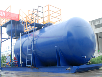
oil tank

How Is Oil Tank Sludge Formed?

Sludge forms when oil is left standing in a tank for an extended period. This causes the oil to separate, with heavier components sinking to the bottom. As the sludge builds up, it can reduce usable space within the tank and increase the risk of corrosion. Furthermore, if the sludge is not treated, it can eventually lead to tank failure and oil spills, which have a significant environmental impact.

Prevention and Inspection

To prevent sludge accumulation, oil tanks should be regularly inspected and cleaned. This can involve draining the tank, removing sediment and impurities, and refilling with fresh oil. However, this process can be time-consuming, expensive, and result in significant downtime. Therefore, an effective oil tank sludge treatment process is essential.

Chemical Cleaning

One common approach to treating oil tank sludge is using chemical agents to break down the sludge into smaller particles for removal. This process, known as chemical cleaning , involves adding a chemical mixture to the tank. The chemicals react with the sludge, breaking it down so it can be pumped out. While this process is effective, it can be costly, and the chemicals used may be harmful to the environment.

Mechanical Cleaning

Another approach to treating oil tank sludge is using mechanical methods. This involves specialized equipment to remove sludge from the bottom of the tank. One common technique is vacuum cleaning , which uses a vacuum truck to remove the sludge. Although this method is effective, it can be time-consuming, and the tank may need to be taken out of service during cleaning.

Bioremediation

A newer approach to the sludge treatment involves the use of biological agents. These agents are specifically designed to break down sludge without harsh chemicals or mechanical cleaning. This process, known as bioremediation , introduces bacteria into the tank that consume the sludge, turning it into harmless by-products. Therefore, this method is environmentally friendly and can be an effective alternative to traditional treatment methods.

Conclusion

Sludge treatment in tanks is an essential process. Sludge buildup can impact tank efficiency and lead to costly repairs and environmental damage. Therefore, it is crucial to have an effective treatment process in place, whether chemical cleaning, mechanical cleaning, or bioremediation. Each method has its advantages and disadvantages, and the appropriate choice depends on facility requirements. However, with proper maintenance and treatment, sludge accumulation can be minimized, and tank efficiency and longevity can be greatly improved.

How KOSUN KSMR-200 Overcomes HDD Mud Recycling Challenges in Confined Jobsites

Mud management directly affects drilling speed and compliance costs on modern jobsites, making an efficient HDD mud recycling system an absolute necessity. Raw mud returning from underground contains large, hard cuttings, while exhibiting high viscosity, easy segregation, and highly variable properties. Without proper purification equipment, crews must dig temporary mud pits or haul away liquid waste.

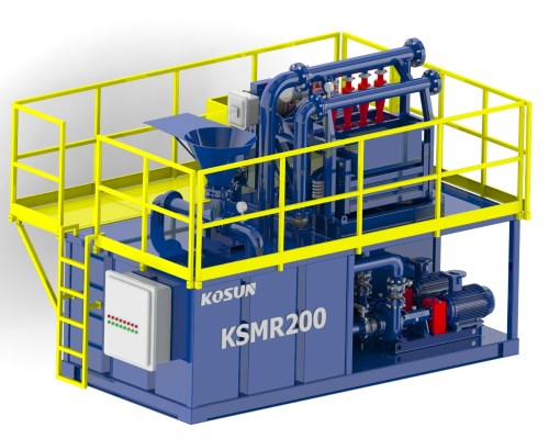
These crude methods create three major industry pain points in narrow urban zones: high fluid chemical costs trim project profits, large solids control equipment cannot fit into restricted spaces, and operators face immediate shutdown risks from strict environmental audits. Therefore, introducing a compact, integrated setup has become essential for contractors to reduce operational costs. This equipment uses modular integration to control drilling waste at the source and enable real-time fluid reuse.KSMR-200 HDD mud recycling system

High-Efficiency Advantages of the KSMR-200 HDD Mud Recycling System

To handle the low displacement and highly restricted spaces of small-to-medium trenchless projects, KOSUN developed a flagship solution: the KSMR-200 HDD mud recycling system. As a top-tier performer in fluid separation, this equipment delivers distinctive structural and technical advantages:

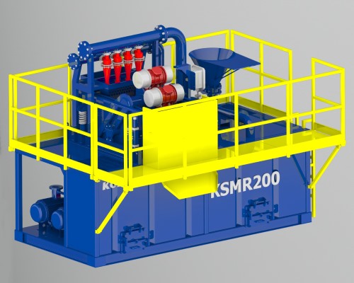
  • Ultra-Compact Modular Integration: Traditional mud purification plants are massive and complex. However, the KSMR-200 condenses multiple functions into a highly concentrated package. It integrates mud cleaning, fluid mixing, and safe storage onto a single steel skid base. The compact frame minimizes the total jobsite footprint to under 15 square meters. This lightweight design allows flatbed trucks to transport the whole unit easily, shortening assembly and teardown times.
  • Dual-Deck Linear Shale Shaker Line of Defense: The core technology relies on the proprietary LS2·752 dual-deck linear shale shaker. Within a very small installation space, the dual-screen configuration gives the slurry higher linear acceleration and multi-stage classification capabilities. Combined with adjustable high G-force trajectories, it completely prevents fluid loss and severe mesh blinding when processing high-viscosity fluids.
  • Micron-Grade High-Precision Purification: Though compact, the system delivers strong fluid dynamics performance. By optimizing hydraulic distribution across the desander and desilter hydrocyclone manifolds, this small HDD mud recycling system maintains a stable processing capacity of up to 50 m³/h. More importantly, it achieves a precise cut point down to 20 microns, extracting harmful fine colloidal solids to prevent excessive wear on downstream high-pressure mud pump fluid ends.KSMR-200 HDD mud recycling system

Closed-Loop Ecology and Value Transformation of the HDD Mud Recycling System

Deploying the KSMR-200 HDD mud recycling system shifts trenchless operations from traditional waste disposal to source-controlled closed-loop processing:

  • 100% Fluid Recycling with Zero Fresh Water Consumption: The system utilizes a self-balancing closed circuit. The clarified mud flows directly to the mixing system to combine with new chemical additives. The mud pump then routes the fluid back to the drilling rig for continuous reuse, eliminating fresh water consumption during operations.
  • Extended Equipment Lifespan and Safety Compliance: All electrical components fully meet international explosion-proof, dust-proof, and rain-proof standards. Critical flow components feature tungsten carbide wear-resistant layers. This heavy-duty engineering ensures stable operations under extreme weather or high sand loads, reducing unplanned jobsite downtime to a minimum.

Conclusion

Instead of focusing on initial purchase costs, industrial fluid processing customers now evaluate total lifecycle costs. A premium HDD mud recycling system that operates efficiently within tight urban footprints provides an essential tool. Ultimately, it helps global drilling companies maximize tunneling efficiency while ensuring strict environmental compliance.

Decanter Centrifuge Selection and Market Trends

The decanter centrifuge acts as critical equipment for closed-loop fluid circulation systems. Facing complex and variable site conditions, modern industrial customers are shifting their equipment selection preferences significantly.

Market Demand Shifts Toward VFD and Long Bowl Centrifuges

Uncertainty in formation structures and fluid properties remains a core pain point for field operations. Fixed-speed equipment fails to balance fine separation with multi-functional operations. The modern market clearly favors variable frequency drive (VFD) centrifuges that feature high-speed shearing and flexible adjustment capabilities.

During different process stages, customers require equipment that adjusts operational parameters flexibly:

  • Barite Recovery Conditions:The system adjusts the decanter centrifuge to low-speed operations [1386]. Relying on a precise low-to-medium separation factor, it efficiently captures and recovers high-density weighting materials, directly cutting new mud preparation costs [1386].
  • Fine Cuttings Removal Conditions:The system operates the centrifuge at high-efficiency separation states. With speeds up to 3900 RPM and G-force up to 3000G, it powerfully removes fine harmful solids above 2 microns, maintaining stable fluid rheological properties.

Furthermore, market demand for long bowl designs continues to increase. Longer bowls extend fluid retention time inside the decanter centrifuge. This process produces drier discharged solids and finer separation cut points, significantly reducing total hazardous waste transportation costs.

Wear Resistance and High Availability of the Centrifuge Under Extreme Loads

Component wear and frequent maintenance shutdowns remain another major pain point for field operators. To ensure continuous operation and extend equipment life, high-quality centrifuge models undergo deep optimization in materials engineering and core supply chains:

  • Hard Carbide Protection for Flow Components:Installing quickly replaceable carbide sleeves at the bowl discharge port protects against erosion. Welding tungsten carbide wear-resistant layers on the screw conveyor flight faces effectively resists micro-cutting wear from high-velocity solid particles.
  • High-Standard Component Supply:Selecting premium bearings from German FAG or Swedish SKF prevents failures. Electrical components fully comply with Siemens or Schneider explosion-proof standards, preventing unplanned shutdowns during long-term, high-speed operations.

Conclusion for Decanter Centrifuge

Instead of focus on initial purchase costs, industrial fluid processing customers now evaluate total lifecycle costs. They increasingly choose decanter centrifuge systems that combine high performance, intelligent adjustments, and hardcore wear-resistant craftsmanship. This approach provides an essential tool for companies to achieve cost reduction and efficiency gains while ensuring strict environmental compliance.

What are the manufacturers of shield muck treatment system in China?

What are the manufacturers of shield muck treatment system in China?

Shield subway tunnel construction process, the waste residue produced by a large amount of waste residue in brings to the urban environment pollution threat, in the city subway tunnel soil balance shield construction, shield tunneling process, in order to ensure the advance smoothly, through the soil of shield machine, add water bentonite, foaming agent, polymer additives, mixing and makes the waste residue have better flow plasticity, achieve balance Graffiti has maintained balance effect.

Due to the characteristics of high mud content and high water content, the slag produced by shield tunneling will inevitably spill and pollute the environment in the process of transportation. In order to timely clean up the soil, a large amount of clean water needs to be consumed when shipping out, and the construction will be blocked because the muck cannot be shipped out in time.

Recently, the shield dregs treatment system produced by KOSUN has been successfully put into operation in Guangzhou Metro project of China and achieved results. The belt conveyor equipment is used to transport the freshly dug dregs from the depth of the tunnel to the feed hopper for separating the ground dregs, and finally separates the coarse and fine sand, realizing the benefit of resource utilization.

KOSUN- China Solids Control Leader&Drilling Waste Management Expert
Email: sales2@adkosun.com
WhatsApp/Wechat:+86 18792396268
Contact person: Lily Wang
Online consulting:
http://www.kosun.com
http://www.kosuneco.com